GoJS是一款功能强大,快速且轻量级的流程图控件,可帮助你在JavaScript 和HTML5 Canvas程序中创建流程图,且极大地简化您的JavaScript / Canvas 程序。
使用Shape类绘制几何图形。您可以控制绘制的形状以及如何描边和填充。
形状,如TextBlock和Picture,是“原子”对象 - 它们不能包含任何其他对象。因此,Shape永远不会绘制一些文本或图像。
在这些简单的演示中,代码以编程方式创建一个Part并将其添加到Diagram中。了解模型和数据绑定后,通常不会以编程方式创建部件(节点或链接)。
数据
您可以将Shape.figure属性设置为常用的形状类型。使用GraphObject.make时,可以将图形名称作为字符串参数传递。您可能还需要设置GraphObject.desiredSize或GraphObject.width和GraphObject.height属性,尽管通常由Panel确定形状所在的大小。
以下是几种最常用的Shape数据:
diagram.add(
$(go.Part, “Horizontal”,
$(go.Shape, “Rectangle”, { width: 40, height: 60, margin: 4, fill: null }),
$(go.Shape, “RoundedRectangle”, { width: 40, height: 60, margin: 4, fill: null }),
$(go.Shape, “Ellipse”, { width: 40, height: 60, margin: 4, fill: null }),
$(go.Shape, “Diamond”, { width: 40, height: 60, margin: 4, fill: null }),
$(go.Shape, “TriangleRight”, { width: 40, height: 60, margin: 4, fill: null }),
$(go.Shape, “TriangleDown”, { width: 40, height: 60, margin: 4, fill: null }),
$(go.Shape, “TriangleLeft”, { width: 40, height: 60, margin: 4, fill: null }),
$(go.Shape, “TriangleUp”, { width: 40, height: 60, margin: 4, fill: null }),
$(go.Shape, “MinusLine”, { width: 40, height: 60, margin: 4, fill: null }),
$(go.Shape, “PlusLine”, { width: 40, height: 60, margin: 4, fill: null }),
$(go.Shape, “XLine”, { width: 40, height: 60, margin: 4, fill: null })
));
您可以在形状样本中看到所有已命名的几何图形 。一些最常用的数字是在GoJS库中预定义的。但是大多数数字都在extensions目录的Figures.js文件中定义。
填充和描边
该Shape.stroke属性指定用于绘制图形的轮廓刷。该Shape.fill属性指定用于填充形状的轮廓刷。额外的“笔划…”属性还控制绘制形状轮廓的方式。最常见的此类属性是Shape.strokeWidth。
diagram.add(
$(go.Part, “Horizontal”,
$(go.Shape, { figure: “Club”, width: 40, height: 40, margin: 4
}), // default fill and stroke are “black”
$(go.Shape, { figure: “Club”, width: 40, height: 40, margin: 4,
fill: “green” }),
$(go.Shape, { figure: “Club”, width: 40, height: 40, margin: 4,
fill: “green”, stroke: null }),
$(go.Shape, { figure: “Club”, width: 40, height: 40, margin: 4,
fill: null, stroke: “green” }),
$(go.Shape, { figure: “Club”, width: 40, height: 40, margin: 4,
fill: null, stroke: “green”, strokeWidth: 3 }),
$(go.Shape, { figure: “Club”, width: 40, height: 40, margin: 4,
fill: null, stroke: “green”, strokeWidth: 6 }),
$(go.Shape, { figure: “Club”, width: 40, height: 40, margin: 4,
fill: “green”, background: “orange” })
));
该Shape.stroke和Shape.fill性质采取刷ES但大多数情况下都获得了CSS颜色字符串来表示纯色画笔。这两个属性默认为纯黑色画笔。但是,将它们中的一个指定为null或“透明”是很常见的。空刷子表示没有为该笔划或填充绘制任何内容。透明刷子产生相同的外观但不同的击中测试行为。具有null Shape.fill的形状会产生“空心”形状 - 在形状内部单击将不会“击中”该形状,因此不会选择游戏下载的节点。但是具有透明填充的形状会产生“填充” “形状 - 形状内的鼠标事件将”击中“
diagram.div.style.background=“lightgray”;
diagram.add(
$(go.Part, “Table”,
$(go.Shape, { row: 0, column: 0, figure: “Club”, width: 60, height: 60, margin: 4,
fill: “green” }),
$(go.TextBlock, “green”, { row: 1, column: 0 }),
$(go.Shape, { row: 0, column: 1, figure: “Club”, width: 60, height: 60, margin: 4,
fill: “white” }),
$(go.TextBlock, “white”, { row: 1, column: 1 }),
$(go.Shape, { row: 0, column: 2, figure: “Club”, width: 60, height: 60, margin: 4,
fill: “transparent” }),
$(go.TextBlock, “transparent”, { row: 1, column: 2 }),
$(go.Shape, { row: 0, column: 3, figure: “Club”, width: 60, height: 60, margin: 4,
fill: null }),
$(go.TextBlock, “null”, { row: 1, column: 3 })
));
尝试在每个形状内单击以查看哪些形状将响应单击并导致选择整个面板。请注意,使用“透明”填充,您可以看到图表背景,但是当您单击它时,您会“点击”形状。只有最后一个,填充为空,才真正“空洞”。单击最后一个形状只会导致图表背景上的单击,除非您单击笔划轮廓。
几何
每个Shape都从它使用的Geometry中获得“形状” 。几何图形只是一个保存的描述,说明如何在给定一组点的情况下绘制一些线条。设置Shape.figure使用可以参数化的命名预定义几何。通常,给Shape一个Geometry而不是给它一个数字是最有效的。
如果你想要一些与GoJS中所有预定义图形不同的东西,你可以构建自己的几何图形并设置Shape.geometry。构建自己的几何体的一种方法是构建由PathSegment组成的PathFigure。在构建基于某些数据计算点的几何时,通常需要这样做。
但是,创建常量几何的更简单方法是调用Geometry.parse来读取具有几何定义路径表达式的字符串,或者将Shape.geometryString设置为这样的字符串。这些表达式具有移动假想“笔”的命令。几何路径的语法记录在“ 几何路径字符串”页面中。
此示例创建一个看起来像字母“W”的Geometry,并在具有不同笔触特征的多个Shape对象中使用它。几何对象可以由多个形状共享。请注意,可能不需要指定GraphObject.desiredSize或GraphObject.width和GraphObject.height,因为Geometry定义了自己的大小。如果设置了大小或由包含Panel强加,则有效几何由Shape.geometryStretch属性确定。根据geometryStretch属性的值,这可能会导致额外的空白空间或剪裁形状。
var W_geometry=go.Geometry.parse(“M 0,0 L 10,50 20,10 30,50 40,0”, false);
diagram.add(
$(go.Part, “Horizontal”,
$(go.Shape, { geometry: W_geometry, strokeWidth: 2 }),
$(go.Shape, { geometry: W_geometry, stroke: “blue”, strokeWidth: 10,
strokeJoin: “miter”, strokeCap: “butt” }),
$(go.Shape, { geometry: W_geometry, stroke: “blue”, strokeWidth: 10,
strokeJoin: “miter”, strokeCap: “round” }),
$(go.Shape, { geometry: W_geometry, stroke: “blue”, strokeWidth: 10,
strokeJoin: “miter”, strokeCap: “square” }),
$(go.Shape, { geometry: W_geometry, stroke: “green”, strokeWidth: 10,
strokeJoin: “bevel”, strokeCap: “butt” }),
$(go.Shape, { geometry: W_geometry, stroke: “green”, strokeWidth: 10,
strokeJoin: “bevel”, strokeCap: “round” }),
$(go.Shape, { geometry: W_geometry, stroke: “green”, strokeWidth: 10,
strokeJoin: “bevel”, strokeCap: “square” }),
$(go.Shape, { geometry: W_geometry, stroke: “red”, strokeWidth: 10,
strokeJoin: “round”, strokeCap: “butt” }),
$(go.Shape, { geometry: W_geometry, stroke: “red”, strokeWidth: 10,
strokeJoin: “round”, strokeCap: “round” }),
$(go.Shape, { geometry: W_geometry, stroke: “red”, strokeWidth: 10,
strokeJoin: “round”, strokeCap: “square” }),
$(go.Shape, { geometry: W_geometry, stroke: “purple”, strokeWidth: 2,
strokeDashArray: [4, 2] }),
$(go.Shape, { geometry: W_geometry, stroke: “purple”, strokeWidth: 2,
strokeDashArray: [6, 6, 2, 2] })
));
角度和比例
除了设置GraphObject.desiredSize或GraphObject.width和GraphObject.height以声明Shape的大小外,还可以设置其他属性以影响外观。例如,您可以设置GraphObject.angle和GraphObject.scale属性。
diagram.add(
$(go.Part, “Table”,
$(go.Shape, { row: 0, column: 1,
figure: “Club”, fill: “green”, width: 40, height: 40,
}), // default angle is zero; default scale is one
$(go.Shape, { row: 0, column: 2,
figure: “Club”, fill: “green”, width: 40, height: 40,
angle: 30 }),
$(go.Shape, { row: 0, column: 3,
figure: “Club”, fill: “green”, width: 40, height: 40,
scale: 1.5 }),
$(go.Shape, { row: 0, column: 4,
figure: “Club”, fill: “green”, width: 40, height: 40,
angle: 30, scale: 1.5 })
));
该Shape.fill和GraphObject.background刷规模,并与形状一起转动。所述
GraphObject.areaBackground绘制在含面板的坐标,所以它不会受该对象的标度或角度。
以下两个形状各自使用三个单独的线性渐变画笔,三个属性各一个。请注意左侧未旋转的形状。由于其GraphObject.background画笔是不透明的,因此您无法看到填充其后面相同区域的
GraphObject.areaBackground画笔。
var bluered=$(go.Brush, “Linear”, { 0.0: “blue”, 1.0: “red” });
var yellowgreen=$(go.Brush, “Linear”, { 0.0: “yellow”, 1.0: “green” });
var grays=$(go.Brush, “Linear”, { 0.0: “black”, 1.0: “lightgray” });
diagram.add(
$(go.Part, “Table”,
$(go.Shape, { row: 0, column: 0,
figure: “Club”, width: 40, height: 40, angle: 0, scale: 1.5,
fill: bluered,
background: yellowgreen,
areaBackground: grays
}),
$(go.Shape, { row: 0, column: 1, width: 10, fill: null, stroke: null }),
$(go.Shape, { row: 0, column: 2,
figure: “Club”, width: 40, height: 40, angle: 45, scale: 1.5,
fill: bluered,
background: yellowgreen,
areaBackground: grays
})
));
自定义数字
如上所示,只需设置Shape.geometry或Shape.geometryString即可轻松创建自定义形状。导入SVG时这非常方便。但是,也可以定义其他命名图形,当您希望通过设置或数据绑定Shape.figure属性来轻松指定或更改现有Shape的几何图形时,这很方便。
静态函数
Shape.defineFigureGenerator可用于定义新的图形名称。第二个参数是一个函数,它使用Shape和预期的宽度和高度调用,以生成并返回几何。这允许基于Shape的属性和预期大小来参数化几何。特别是,除了宽度和高度之外,还可以在生成Geometry时考虑Shape.parameter1和Shape.parameter2属性。为了有效,生成的几何边界必须等于或小于提供的宽度和高度。
go.Shape.defineFigureGenerator(“RoundedTopRectangle”, function(shape, w, h) {
// this figure takes one parameter, the size of the corner
var p1=5; // default corner size
if (shape !==null) {
var param1=shape.parameter1;
if (!isNaN(param1) && param1 >=0) p1=param1; // can’t be negative or NaN
}
p1=Math.min(p1, w / 2);
p1=Math.min(p1, h / 2); // limit by whole height or by half height?
var geo=new go.Geometry();
// a single figure consisting of straight lines and quarter-circle arcs
geo.add(new go.PathFigure(0, p1)
.add(new go.PathSegment(go.PathSegment.Arc, 180, 90, p1, p1, p1, p1))
.add(new go.PathSegment(go.PathSegment.Line, w - p1, 0))
.add(new go.PathSegment(go.PathSegment.Arc, 270, 90, w - p1, p1, p1, p1))
.add(new go.PathSegment(go.PathSegment.Line, w, h))
.add(new go.PathSegment(go.PathSegment.Line, 0, h).close()));
// don’t intersect with two top corners when used in an “Auto” Panel
geo.spot1=new go.Spot(0, 0, 0.3 * p1, 0.3 * p1);
geo.spot2=new go.Spot(1, 1, -0.3 * p1, 0);
return geo;
});
go.Shape.defineFigureGenerator(“RoundedBottomRectangle”, function(shape, w, h) {
// this figure takes one parameter, the size of the corner
var p1=5; // default corner size
if (shape !==null) {
var param1=shape.parameter1;
if (!isNaN(param1) && param1 >=0) p1=param1; // can’t be negative or NaN
}
p1=Math.min(p1, w / 2);
p1=Math.min(p1, h / 2); // limit by whole height or by half height?
var geo=new go.Geometry();
// a single figure consisting of straight lines and quarter-circle arcs
geo.add(new go.PathFigure(0, 0)
.add(new go.PathSegment(go.PathSegment.Line, w, 0))
.add(new go.PathSegment(go.PathSegment.Line, w, h - p1))
.add(new go.PathSegment(go.PathSegment.Arc, 0, 90, w - p1, h - p1, p1, p1))
.add(new go.PathSegment(go.PathSegment.Line, p1, h))
.add(new go.PathSegment(go.PathSegment.Arc, 90, 90, p1, h - p1, p1, p1).close()));
// don’t intersect with two bottom corners when used in an “Auto” Panel
geo.spot1=new go.Spot(0, 0, 0.3 * p1, 0);
geo.spot2=new go.Spot(1, 1, -0.3 * p1, -0.3 * p1);
return geo;
});
diagram.nodeTemplate=$(go.Part, “Spot”,
{
selectionAdorned: false, // don’t show the standard selection handle
resizable: true, resizeObjectName: “SHAPE”, // user can resize the Shape
rotatable: true, rotateObjectName: “SHAPE”, // user can rotate the Shape
// without rotating the label
},
$(go.Shape,
{
name: “SHAPE”,
fill: $(go.Brush, “Linear”, { 0.0: “white”, 1.0: “gray” }),
desiredSize: new go.Size(100, 50)
},
new go.Binding(“figure”, “fig”),
new go.Binding(“parameter1”, “p1”)),
$(go.Panel, “Vertical”,
$(go.TextBlock,
new go.Binding(“text”, “fig”)),
$(go.TextBlock, { stroke: “blue” },
new go.Binding(“text”, “parameter1”, function(p1) { return p1; }).ofObject(“SHAPE”))
)
);
diagram.model=new go.Model([
{ fig: “RoundedTopRectangle” },
{ fig: “RoundedTopRectangle”, p1: 0 },
{ fig: “RoundedTopRectangle”, p1: 3 },
{ fig: “RoundedTopRectangle”, p1: 10 },
{ fig: “RoundedTopRectangle”, p1: 50 },
{ fig: “RoundedTopRectangle”, p1: 250 },
{ fig: “RoundedBottomRectangle” },
{ fig: “RoundedBottomRectangle”, p1: 0 },
{ fig: “RoundedBottomRectangle”, p1: 3 },
{ fig: “RoundedBottomRectangle”, p1: 10 },
{ fig: “RoundedBottomRectangle”, p1: 50 },
{ fig: “RoundedBottomRectangle”, p1: 250 }
]);
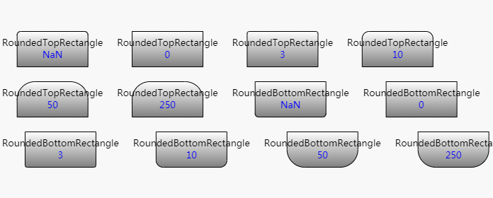
请注意Shape.parameter1属性(绑定到“p1”属性的数据)如何控制角的舍入程度。每个图形的定义根据几何体的实际大小限制圆度。您可以通过调整最后一个形状的大小来查看效果 - 如果形状变大,则p1==250的形状上的曲线可能很大。

 随时随地看视频


